Design Tips For Sheet Metal

Design Tips for Sheet Metal Bending

Various kinds of operation processes for the sheet metal fabrication from eco rapid

Bending is a form of deformation, one of three primary processes in sheet metal fabrication; the other two being cutting and joining. Bending is done by holding the workpiece in position using clamps or dies and strategically applying force on an area of a workpiece. The force applied must exceed the yield strength of the material to cause the plastic deformation of the part. This process results in a v-shape, u-shape, or channel shape over an axis, creating a new part geometry. Bending changes the shape but the volume of the workpiece remains the same.

Types of Sheet Metal Bending

There are various methods for sheet metal bending. They are:

Air bending: This makes use of two dies; the upper die (also known as the punch) and the bottom die. The bottom die has a V-shaped opening. The punch forces the sheet metal into the bottom die. Air bending is not as precise as other methods.

Bottoming: In this method, the sheet metal is pressed onto the surface of the die by the punch. The metal then takes up the final angle, same as that of the die. For sheets about 3mm thick, the optimum width for the v-die opening is 6x the material thickness and about 12x the material thickness for 12mm thick sheets.

Coining: This is similar to air bending. However, the force used is usually 5 to 30 times the force for air bending. This gives a much higher precision.

Folding: Clamping beams are used to hold the longer side of the metal. The beam is free to rise and bend the sheet around a bend profile. Both negative and positive bend angles are possible.

Wiping: The longer side of the sheet is clamped, and a tool moves up and down, bending the metal around the bend profile. Wiping is relatively faster than folding but has a higher tendency of producing scratches or damaging the sheet.

Rotary bending: The top die is made of a cylinder that is free to rotate. The final shape for the bend is cut into it, and a matching bottom die. As the rolls contact the sheet, it rotates. The process bends the sheet.

Joggle bending: This is an offset bending. The two opposite bends are less than 90 degrees each. A neutral web separates the opposite bends.

Design Tips for Bending

To ensure a hitch-free bend and to avoid deformation, the following 10 tips are vital when designing.

1. Part thickness

Parts must have a uniform wall thickness throughout. Eco Rapid is capable of manufacturing bent sheet metal parts up to 6.35mm in thickness, but this tolerance mainly depends on the geometry

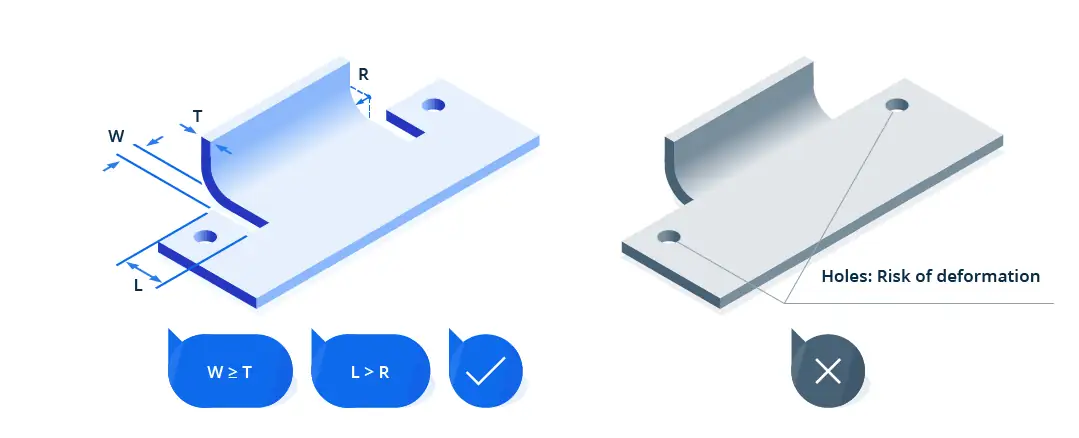
2. Hole and slot clearance

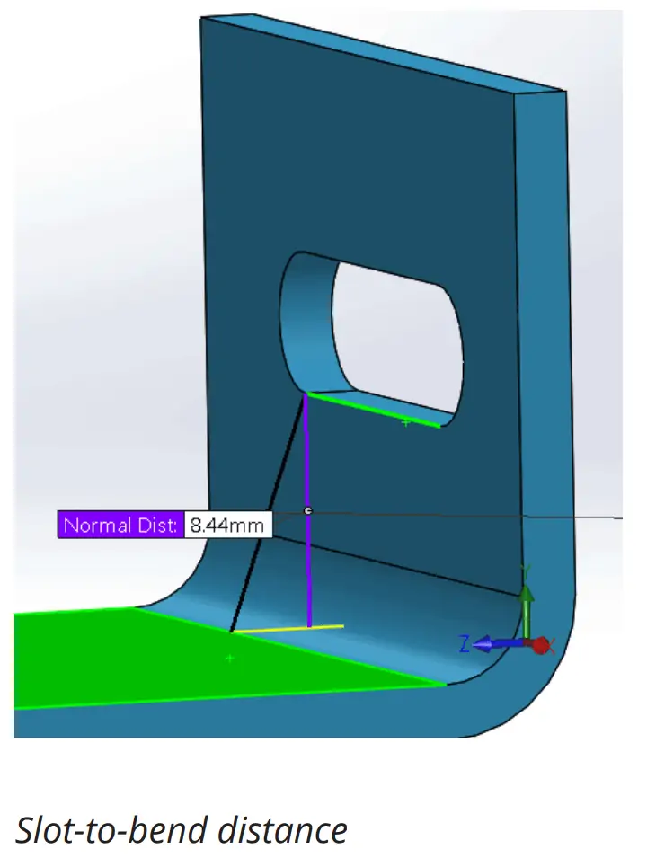
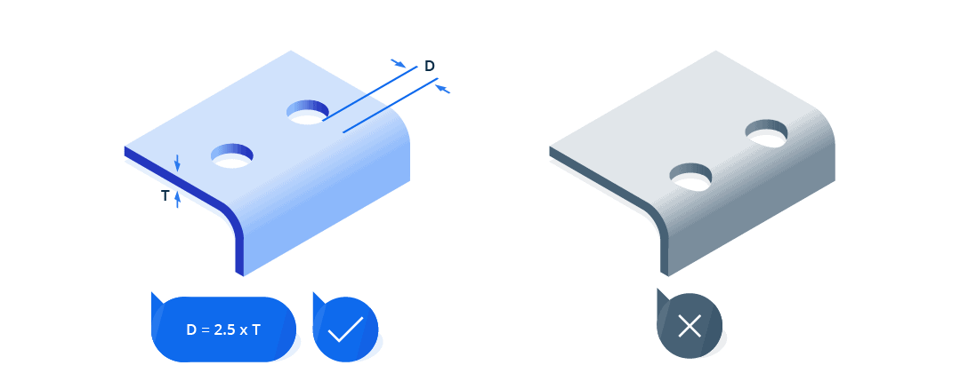
The distance of holes from the bend should be at least 2.5x the material thickness. Slots require more clearance. Slots should be placed at a distance of at least 4x the material thickness from the bend edges. This is because holes and slots are likely to deform when placed near a bend. Also, to avoid a bulging effect, place these features at a distance of at least 2x the material thickness from part edges.

3. Bend radius

The radius of bends must be a minimum of 1x the material thickness to prevent parts from fracturing or distorting. Also, the Bend radius should be kept consistent to minimize cost.

All bends in the same plane should be designed in one direction to prevent part reorientation. This saves both money and time.

Large, thick parts should not have small bends due to the high tendency to become inaccurate. As a rule of thumb, the inside bend radius should at least equal to the material thickness.

4. Curls

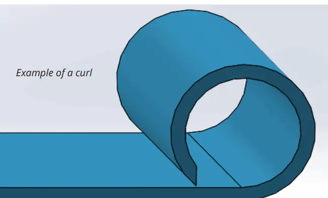
The outside radius of curls must be at least twice the material thickness.

In addition, the distance of holes from curls should be at least equal to the curl radius plus the material thickness. Other bends should be placed away from the curl at a distance of at least 6x the material thickness plus the curl radius.

5. Clearance for countersink

Countersinks on sheet metal parts are usually produced with hand tools. They must not be deeper than 0.6x the material thickness. This means that the maximum depth of a countersink in a 10 mm thick material should be 6 mm.

Furthermore, countersinks must have a minimum distance of 3x the material thickness from a bend, 4x from an edge, and 8x from each other.

6. Hems

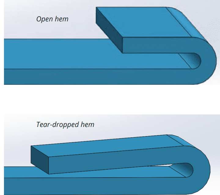
Hems are folds created at the edge of parts to create a safe, rounded edge. There are three hem designs with different design rules.

For open hems, the minimum inside diameter should be at least equal to the material thickness, as larger diameters will cause loss of circularity. To ensure a perfect bend, the return length should be 4x the material thickness.

Teardrop hems should also have a minimum inside diameter that is equal to the material thickness. The opening should be a minimum of ¼x the material thickness, while the run length should be at least 4x the material thickness following the radius.

7. Chamfered sides

Chamfers on flanges must leave enough room for bends to avoid deformed parts.

8. Bends next to each other

Successive bends should be avoided except when absolutely necessary. A common problem for successive bends is the difficulty to fit the already bent parts on the die. However, when unavoidable, the intermediate part should be longer than the flanges.

9. Clearance for notches and tabs

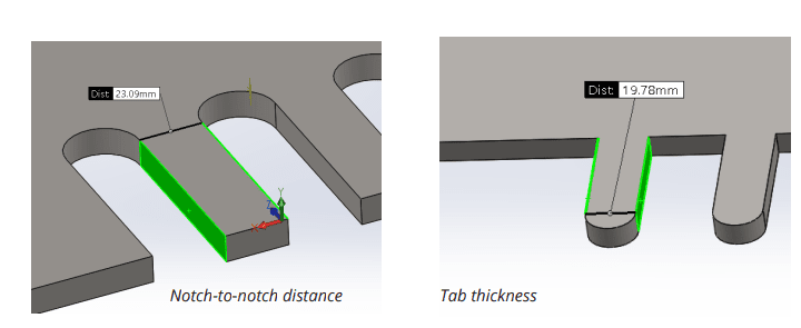
The notch to bend distance should be at least 3x the material thickness plus the radius of the bend. Tabs, on the other hand, must be 1 mm or the material thickness away from each other, whichever value is greatest.

10. Relief cuts

Relief cuts are essential in avoiding bulging and tearing at bends. The width of the relief cuts should at least be equal to the material thickness, and the length should be longer than the radius of the bend.

Calculating Required Bending Force

Different factors are involved in creating the right bend in a workpiece. These include:

  • Bending strength of the material
  • Degree of bending
  • Thickness of the workpiece
  • Bend angle
  • Internal radius
  • Vee die opening
  • Minimum internal edge

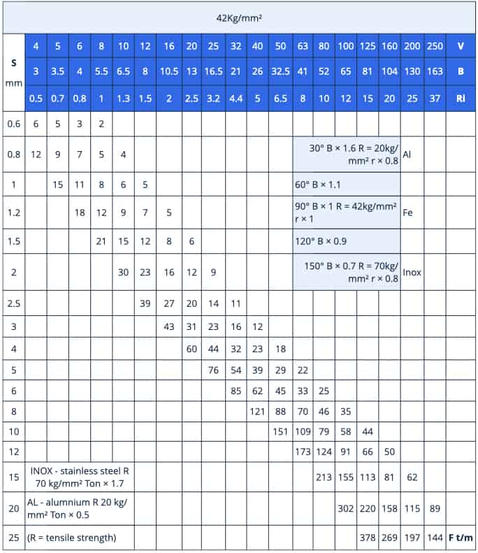
The chart below can be used to calculate the bending force required to V bend mild steel S235 of different thicknesses, in different shapes, at an angle of 90°. Mild steel S235 has a bending strength of 42 kg/mm². The variable parameters are as follows.

  • S (mm) – Thickness of the workpiece
  • V (mm) – Vee die opening
  • B (mm) – Minimum internal edge
  • Ri (mm) – Internal radius

Conclusion

At Eco Rapid, we offer high-precision, fast, and quality sheet metal bending and fabrication services for the creation of parts out of sheet metal such as aluminium, steel, copper alloys, and many others. Using automated bending techniques, we guarantee high precision and quality of ready parts. Simply contact us and get a free quote.

Design Tips For 3D Printing

Infographic: Design Rules for 3D Printing Technology

3D printing offers a unique combination of design freedom and ease of reproduction

In the space of a few hours. You can come up with your won unique 3D model and turn it into a physical object. All without the use of expensive molds and heavy-duty machining tools.
However, not all 3D models translate well into 3D printed objects. Some may be harder to pull off than the others. If you’re designing your own models for 3D printing, there are certain factors that you will need to consider. To help you plan ahead, there are some of the best tips from 3D printing and modeling experts.

  1. Reduce Supports By Following The 45-degree Rule.
    Overhanging features aren’t really huge issues when it comes to 3D printing. Because you can easily remedy the problem by adding support structures. However many 3D printing professionals consider the addition of support as a last resort. Not only do they consume a substantial amount of filament. But the process of removing them may damage the finished print or result in uneven surfaces.
    If you are designing your own model. Then you can make a couple of deliberate decisions to reduce the need for supports. The 45-degree rule is one that’s easy to follow and remember. Any incline that goes beyond 45-degrees will need a support structure to support its weight. If necessary, you can also add a chamfer, which is a wider incline split into 45-degree segments. Even pushing the 45-degree boundary would be pushing the limitations of the strength of the filament material. So we suggest keeping all inclines close to only around 30 degrees.
  2. Get Clearances Right
    If you’re looking for create mechanical fitting parts. This step is essential, no machine is perfectly precise. And 3D printers tend to be less precise than other manufacturing technologies.
    This means that parts you design must have proper clearances or gaps between each other to guarantee a fit. For instance, if you have a mount that is intended to hold a bearing. The hole you design for the bearing should be slightly larger than the bearing itself. That way, even if the print has few small artifacts on its surface, the bearing will still fit.
    Find the clearances you need for your printer, and don’t forget to include them in your designs!
  3. Mind Overhangs
    In 3D printing, objects are created from the ground up, usually in a layer-by-layer process. This means that features hanging in mid-air don’t fare too well. Becoming deformed or separating from the rest of the model.
    The solution supports structures, they prop up overhanging areas to retain their intended shape. Different 3D printing technologies have different support requirements. SLA printing for instance, almost always demands supports. While in SLS the plastic powder used for printing also doubles as the support material. In FDM, the most common technology supports are required based on the model’s geometry. Which has a significant effect on printing and post-processing time. To avoid the hassle, keep an eye overhanging areas when designing models for this technology. A good rule of thumb is to not to exceed 45-degrees when possible. It’s an extra bit of work, but minding overhangs will save you loads of time in post-processing your print.
  4. Orient Based On Resolution And Strength
    3D prints made using FDM technology naturally come out with visible layer lines. This is an inherent consequence of the reliance of FDM printers on relatively wide nozzles. However, the resolution along the z-axis can somewhat be controlled by setting the thickness of these layers. Resolution on the x-axis and y-axis, However, is determined by the size of the nozzle. This is something you may need to consider if your model has very fine details. If you want precise details in your model. Then it would be best to have those details oriented along the z-axis. While it’s true that models can be rotated any axis in the slicer software. You still need to keep in mind that resolution is not equal among all three axes. If you are designing a part that is meant to bear a significant load. You may also need to consider the strength limitations of FDM printing. Basically, the layer lines are the print’s weakest points. Aany stress parallel to them can cause them to get pulled apart from each other. For best results. It would be best to design your model so that any stress is applied perpendicular to the layer lines.
  5. Split The Model Into Multiple Parts
    If you are designing a model for printing on a desktop 3D printer. Then the limitation on build size is something you may need to consider. After all, your 3D printer may not be large enough to create that action figure or prop you’re designing.
    Splitting the model into multiple parts can also be advantageous. If you want to avoid having too many support structures on your print. For instance, splitting the model into two or three parts. And orienting them in different directions may mean each part would have fewer overhanging features. This is worth the effort just to avoid the hassle and extra filament that support structures demand.
    There are a couple of different ways that you can split apart a model. You can simply cut them in certain sections. Which means you’ll need to glue the parts together once they are all printed. You can also design snap-fit or press-fit connections, which have the advantage of being non-permanent. The second option can be useful for large props or prototypes. That you’ll need to take apart for transportation and put together again, such as those used in conventions or exhibits.
  6. Consider 3D printer Tolerances Based On Nozzle Size
    There’s only so much detail that a 3D printer can reproduce, especially given the size of its nozzle. This holds true for any axis. Moreover, plastic filament naturally expands as it cools. This phenomenon is something you’ll need to consider when managing your expectations of how detailed a model can be when printed. A good rule of thumb to follow is that the effective size of a filament when it is extruded and cooled is around 1,2 times the diameter of the nozzle. For a standard 0.4-millimeter nozzle, this translates to 0.48 millimeters. This means that the features of your model need to be at least 0.48 millimeters or larger on each aixs.
    Tolerance refers to the distance between two nearby features that is just large enough for them to not fuse with each other. Again, the effect of thermal expansion is something you’ll need to consider when designing for tolerances. The problem is that there isn’t a single tolerance value that applies to all filament material and nozzle sizes. Your best bet would be to print this test template to check for the acceptable tolerance for your setup.
  7. Consider The Material
    If you know the 3D printing technology you’ll be using, You’ll also know the materials available to you. Like printers, different materials have their own unique properties. When designing you model, account for there properties.
    In FDM printing, for instance, ABS plastic is prone to warping, so your design’s base should be large enough to stay attached to the build plate. Flexibles don’t do too well with details, so maybe omit small features. These will all decrease chances of print failure.
    Additionally, keep manufacturer specifications in mind. The same material produced by different manufacturers can behave differently, so always refer to the printing instructions and profiles provided with the material.
    Take material considerations into account for a smooth printing experience.
  8. Avoid Warping By Removing Sharp Corners
    Add mouse ears to your model Warping in one of the biggest problems that a 3D printing professional can encounter. This is especially true when printing with high-temperature filaments, such as ABS or Nylon. Solving the warping issue takes a monumental effort, from tweaking the temperature settings to painstakingly applying adhesives to the print bed. Fortunately, you can take steps in the design process to stave off the warping problem.
    The most common manifestation of warping is when the corners of the base layers of the print lift off the print bed. The corners are especially prone, as these are the point where the thermal stress generated by thermal contraction accumulate.
    One of the smartest ways to avoid warping is to avoid this accumulation of thermal stress by designing rounded corners. This results in a more even distribution of thermal stress not only on the base layer but also for the rest of the print.
    While using rounded corners is not an assurance that you will no longer run into a warping problem, it should help avoid the issue from manifesting.
  9. Add Mouse Ears To Your Design
    Use “mouse ears”, helper disks and cones designed into you model to help it print without the use of computer generated supports.
    Mouse ears are basically small disks located on the corners of the base layer of the model. The idea is to increase the surface contact between the corners of the model and print bed in bid to prevent these corner from lifting off. Some slicer software platforms offer the option to add mouse ears to models before printing, although not many of them do. In the case of the letter, mouse ears will have to be added to the original 3D model. The use of mouse ears allows you to retain the sharp edges in your model. However, you’ll have to live with the fact that your finished print will have mouse ears on it base. It would be a good idea to integrate mouse ears into the overall aesthetic of your design. Unlike support structures, mouse ears are practically impossible to remove without ruining the rest of your print.
  10. Watch File Quality
    Before 3D printing, your design must be converted to a 3D printable file. During this process, there are few key items to note:
    Ensure that your converted file is of sufficient quality. The above image demonstrates the importance of this: a higher-quality file will be larger, but will be more geometrically accurate. This is especially significant when you have small features, which are sometimes completely omitted when file quality is low.
    Check that the file is “watertight”. This means that is has no holes in it that could confuse your slicing software. A powerful free tool for this is MeshMixer from Autodesk.
    Scale your model before exporting. This will prevent detail loss caused by scaling up your model after the fact. This is like how a low-resolution image looks fine when it is small, but becomes pixelated when you make it larger. Models exported before being scaled may seem fine when left alone, but can totally fall apart when you try to scale them later.
    Any design, However impressive, can be laid low by file errors. Watch for file quality to get the best results!

If you are interested in to know more technology about 3D printing, feel free to reach out with us at eco@eco-rp.com or 8613712611558

The titanium alloy materials and products

The development characteristics of processing technology for titanium alloy materials and products

What can titanium be used for?

Titanium has a number of useful properties. For example, it’s strong, corrosion-resistant and has an exceptionally high melting point – as a result. It lends itself well to a broad range of applications.

Commonly alloyed with other metals (e.g. iron, aluminium, molybdenum). It can be fabricated into a variety of parts and fittings and is used across many different sectors.

For example, titanium metal is commonly seen in:

1. Aerospace and military – due to its excellent strength (and low density). It’s frequently used to create jet engines, aeroplanes, spacecraft, missiles and other similar structures.

2. Industrial processes – resistant to many corrosive substances, it’s often employed in chemical and petrochemical plants. It’s also often used for desalination plants. Where it can help to protect the hull of ships. submarines. and other structures that are exposed to seawater.

3. The medical industry – non-toxic and non-allergenic. Titanium is regularly used to make medical instruments and to create medical prostheses, orthopaedic implants, and dental implants.

Due to the high manufacturing cost of titanium alloy. In order to reduce the cost. The competitiveness of titanium alloy in the whole metal material market with a lower price. Titanium is widely considered to offer unrivalled performance compared with other materials. But its price is often prohibitive to consumers, especially automakers. The appearance of high quality and low cost titanium alloy. Will certainly contribute to the popularization and application of titanium and titanium alloy. From the application status at home and abroad and the development of titanium processing technology. The plastic processing technology of titanium and titanium alloy will develop in the following directions in the future.

1) High performance, Namely the development of alloys with Higher service temperature. Higher specific strength. Higher specific modulus. Better corrosion resistance and wear resistance.
2) Multi-functional, that is the development of titanium alloys with various special functions and uses. Such as high damping, low expansion, constant resistance, high resistance, anti-electrolysis passivation and hydrogen storage. Shape memory, superconductivity, low modulus biomedical titanium alloys, and further expand the application of titanium and titanium alloys.
3) Deepen the research or traditional alloy. Improve the practical properties of existing alloys. And expand the application range of traditional alloys through the improvement of equipment and process.
4) Using advanced processing technology. Large continuous processing equipment. Developing continuous processing technology. Direct rolling technology, cold forming technology and near net forming technology. Improve the production efficiency, yield and product performance of titanium alloy.
5) Reduce costs. Develop alloys with no or little precious metal elements. And add cheap elements such as Iron. Oxygen and Nitrogen. Develop titanium alloys that are easy to process and shape, easy to cut, alloy elements and parent alloys are cheap. To develop titanium alloy and improve the recovery and utilization rate of banned titanium by using banned materials. This is particularly important to reduce the cost of civil titanium alloy.
6) Using advanced computer technology to simulate the deformation and processing process of the workpiece. To predict the evolution of metal microstructure, and even to predict the mechanical properties of the product. (yield strength, tensile strength, elongation and hardness, etc). And design or improve tooling and analyze and process test results to reduce text volume. Improve work efficiency and reduce development cost.

Find more technical issues about CNC Machining3D PrintingSheet MetalVacuum CastingAluminum ExtrusionRapid Injection Molding.

Please feel free to reach out with us at eco@eco-rp.com and +86 137 1261 1558

Design Tips For CNC Machining

10 tips to improve your CAD designs for CNC machining

The design process for CNC machining requires precision and accuracy to produce quality designs.

This is why there are recommended general design rules that apply to the most common features of CNC machined parts.

1. Avoid designing excessively thin walls

Thin walls are a requirement for certain engineering projects such as drone parts or whistles. Avoiding excessively thin walls would improve your models when designing for CNC Machining. Studies have shown that wall thickness is proportional to the stiffness of the material, therefore lowering the wall thickness would also lower the stiffness of the material hence reducing achievable accuracy as a result of inevitable vibrations during machining. The standard minimum thickness for walls is 0.794 mm for metals and 1.5 mm for plastics.

In cases where designing such thin walls are necessary, employing other manufacturing processes like sheet metal fabrication is advisable and economical.

2. Avoid designing features that cannot be CNC machined

Not all features can be machined. Similar to thin walls, unnecessary features would only make designs difficult to machine. Knowing the machine’s capabilities is often an advantage when designing for CNC Machining, as this would help you design features producible by the machine.

An example of an impossible to machine feature which cannot be produced with CNC mills, lathes or drills is “curved holes”. However, if this feature, as well as other impossible to machine features, are necessary for your design, electrical discharge machining (EDM) may be used.

3. Avoid excessive use of tolerances

Designers are expected to tolerance dimensions where necessary. But it is important to note that excessive tolerancing would only increase machining time and cost. Different CNC machines have different tolerance standards, therefore if your dimensions have no tolerancing, the machine would use its standard tolerance for such dimensions. To save time and cost, tight tolerances should only be specified when necessary as they are. It is also important to maintain homogeneous tolerancing as this would reduce machining time.

Avoid excessive use of tolerances

4. Avoid designing unnecessary aesthetic features

As stated in the aforementioned ways to improve CAD designs, some features are only aesthetic and cannot be efficiently machined. Before removing parts for just looks, it is important to consider the amount of material to be removed and the process to be used in doing this. As a designer, you should always consider questions like “what process would this feature require?” or “is it a 5-axis or a 3-axis machining process?”. You can improve your design by paying attention to the accuracy of necessary features rather than aesthetics seeing as post-machining processes such as electro-polishing could be used to achieve aesthetics.

5. Design cavities with accurate depth-to-width ratios

You can improve your design by taking into consideration, depth to width ratio of cavities when designing cavities. Too deep cavities would result in the tool hanging, tool deflection, difficulty in chip evacuation, and tool fracture.

Cavities higher than six times the tool diameter are considered deep, and should have a maximum depth of four times the width of the cavity. For example, a 15 mm wide cavity should not be more than 60 mm deep.

6. Add radii when designing internal edges

Designing internal edges can be stressful on the machining tool considering its shape. Since most cutting tools are cylindrical and cannot machine sharp internal edges, it is important to add radii to internal edges in your design. To avoid wear and tear of the tool, it is necessary to design internal edges that would not stress the tool more than necessary. In order to achieve this, a good rule of thumb is to add a radius of 130% of the milling tool radius. If your milling tool has a radius of 5 mm, it is recommended that you add a radius of 6.5 mm to all your internal angles. This additional radius would reduce stress on the tool and increase cutting speed. 

  • Recommended: R > D/3
  • Minimum: R > 1.3 tool diameter

If 90 degrees internal edges are your design requirements, you can add an undercut as opposed to reducing the edge radius.

7. Limit thread length

It is common engineering knowledge that strong thread connections take place in the first few threads. Therefore, very long threads are sometimes completely unnecessary. When designing tapped holes, you can improve your design by designing just sufficiently long thread lengths. A thread longer than 3 times the hole diameter is unnecessary.

However, when designing for blind holes, it is advisable to add an unthreaded length at the bottom of the hole and when a CNC threading tool is used, the hole can be fully threaded.

8. Avoid designing too small features

Most CNC machines have a minimum tool diameter of 2.5mm, therefore any feature smaller than 2.5mm would be difficult to machine. Too small features would require a special tool and this would increase machine costs and time. Therefore too small features should be avoided except when necessary.

9. Design holes with standard sizes

Standard sized holes are milled using standard drill bit sizes. This saves machine time and cost as holes not designed to standard would require an end mill tool.

In the case of non-standard holes, the rule of thumb for depth of cavity must be applied, which is the depth must be four times the diameter of the cavity.

Design holes with standard sizes

10. Avoid unnecessary text and lettering

Designing parts with text and lettering is unnecessary. Any required texts can be painted on the surface of the machined part during finishing. Designing texts for machining would only increase machine time and cost.

However, if text and lettering are design requirements, the following rules should be followed:

  • Engraved texts should be used as less material is removed in this case.
  • If your design software does not have a custom lettering font, then the San Serif font with 20 points is recommended. This is because this font does not have extra lines (serif) at the end of each lettering stroke. These extra strokes increase machining cost. Also, size 20 is recommended because sizes smaller than this are considered small feature which are more difficult and costly to machine.

Find more technical issues about CNC Machining3D PrintingSheet MetalVacuum CastingAluminum ExtrusionRapid Injection Molding.

Please feel free to reach out with us at eco@eco-rp.com and +86 137 1261 1558

EN/FR/DE/IL/RU/ES

Eco - Rapid Prototyping

Eco industrial has been established since 2012, Office located at Dongguan City,Guangdong Province, China.
We have over 10 years of professional experience in supplying precision metal and plastic parts and fittings for Aerospace, Automotive, Robotic, Energy, Medical device, Consumption goods, etc industries.